Understanding the intricacies of microinverter schematics provides a significant advantage when navigating the rapidly evolving solar energy industry. As energy consumption patterns shift towards sustainability, the microinverter gains popularity for its efficiency and adaptability in solar power systems. This article delves deep into the microinverter schematic, combining expert insights, experience-based observations, and authoritative references to provide a comprehensive guide.
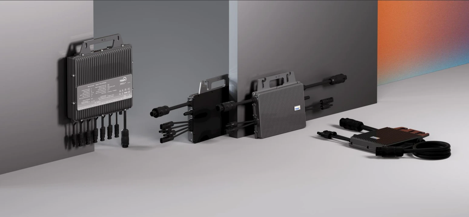
Microinverters, unlike traditional string inverters, are installed at each solar panel to convert direct current (DC) into alternating current (AC) right at the source. This localized conversion is paramount in maximizing energy output, particularly in installations where panels face different directions or suffer from partial shading.
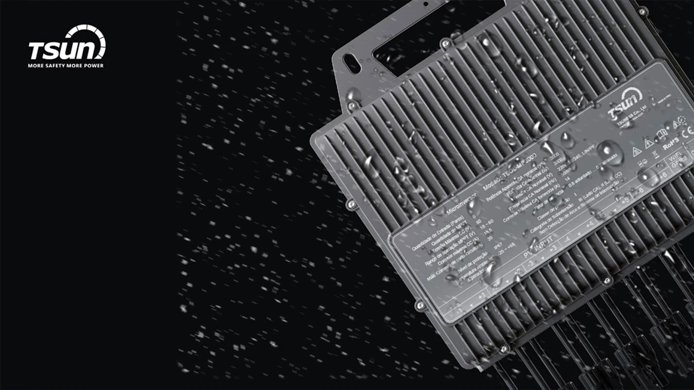
The schematic of a microinverter is emblematic of its advanced operational prowess.
At the core of a microinverter schematic lies a focus on modularity and efficiency. Key components include the power conversion units, such as the DC-AC inverter circuitry, which features a high-frequency transformer. This transformer plays a crucial role in adjusting the voltage levels between the panel and grid, ensuring smooth energy flow and grid stability. Experienced engineers often highlight the importance of this component in influencing the lifetime and reliability of the microinverter system.
In addition to the inverter circuitry, most schematics include detailed layouts of MPPT (Maximum Power Point Tracking) algorithms. Trust in a microinverter's efficiency is heavily reliant on its MPPT capabilities, which constantly optimize the power output from each panel regardless of external conditions. Expert installers recognize products with sophisticated MPPT to achieve higher yields and more stable outputs, even under less-than-ideal conditions.
microinverter schematic
The schematic further expands with control systems that ensure operational synchronization with the broader energy grid. These often feature detailed designs of embedded communication units, which are essential for monitoring and managing the inverter's performance in real-time. This aspect of the schematic underscores the system’s authority and reliability, as it reflects advanced engineering practices designed to meet stringent safety and compatibility standards.
For professionals in the field, integrating experience with understanding of microinverter schematics cultivates an authoritative perspective on installation and maintenance. Technical manuals often overlook the nuances of component interplay seen in real-world applications. For instance, the heat dissipation pathways indicated in the schematic are critical for ensuring longevity and performance stability. Overheating is a common issue that practical experience highlights, yet it may not be detailed adequately in standard documentation. Thus, seasoned installers advocate for layouts incorporating generous thermal margins and enhanced material durability to tackle these concerns.
Moreover, the schematic’s emphasis on modularity does not only aid individual component maintenance and replacement but also presents scalability. As energy needs grow, the architectural flexibility depicted allows for seamless integration of additional units without requiring overhaul, a testament to the system's forward-thinking design.
In conclusion, the schema of a microinverter embodies both complexity and simplicity, merging refined engineering with user-friendly modularity. Whether approached from an expert angle of design evaluation or through practical lessons drawn from deployment experiences, the schematic remains a fundamental tool. For those seeking reliability and efficiency in solar installations, choosing microinverters supported by a comprehensive and authoritative schematic is indispensable. As the sector grows, refining these designs continues to build trust and spur innovation, meeting the pressing demands for cleaner, reliable energy solutions.


")


")

 LEARN DETAILS


 Downloads
 Video Center
 Report Fault for Repair
 FAQS
FAQS Service Network
 Privacy Policy
 Contact us
 Monitoring


 LEARN MORE